COB vs SMD LED Strip: Architectural LED Strip Lighting
2026-05-27

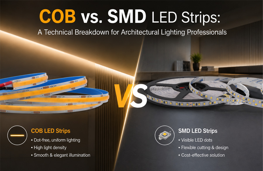
COB vs. SMD LED Strips : A Technical Breakdown for Architectural Lighting Professionals

COB vs. SMD LED Strips: A Technical Breakdown for Architectural Lighting Professionals

Architectural lighting specification demands precision, photometric consistency, and predictable lifecycle performance. The choice between COB (Chip-on-Board) and SMD (Surface-Mount Device) LED strips is no longer a matter of brightness or price—it is a technical decision impacting visual comfort, thermal dynamics, installation tolerances, and long-term maintenance costs. Lighting designers, electrical engineers, contractors, and procurement specialists require actionable data, not marketing claims.
Core Architecture: SMD vs. COB LED Strip Technology
Photometric Performance & Visual Quality
Thermal Management & Longevity
Electrical & Installation Considerations
Application-Specific Selection Guide
Cost, ROI & Procurement Strategy
Future Trends & Industry Standards
Summary
FAQ

Core Architecture: SMD vs. COB LED Strip Technology

Understanding the physical and electrical architecture is the foundation for accurate specification. The structural differences dictate optical behavior, thermal pathways, repairability, and installation constraints.

SMD (Surface-Mount Device) Architecture

  • Discrete LED packages mounted on flexible or rigid PCB via reflow soldering
  • Each emitter contains individual phosphor-coated silicone lenses and copper heat slugs
  • Typical emitter spacing: 3mm to 10mm depending on density (e.g., 60/m, 120/m, 240/m)
  • PCB traces route current between components; cut points available at predefined intervals
  • Encapsulation: Epoxy or silicone overmolding for IP rating, independent of LED package
  • Repairability: Single-failure isolation possible; localized replacement feasible
  • Manufacturing yield: High tolerance for component variance; binning required for color consistency
SMD (Surface-Mount Device) Architecture

COB (Chip-on-Board) Architecture

  • Bare LED chips directly bonded to aluminum or ceramic substrate using die-attach adhesive
  • Phosphor-resin matrix cast uniformly over entire chip array
  • Continuous light-emitting surface; emitter spacing effectively <1mm
  • Electrical routing integrated into substrate; cut points limited or factory-defined
  • Encapsulation: Single silicone dome or flat resin layer covers entire active area
  • Repairability: Non-modular; entire section fails if thermal or electrical fault occurs
  • Manufacturing yield: Tighter process control required; phosphor coating uniformity critical
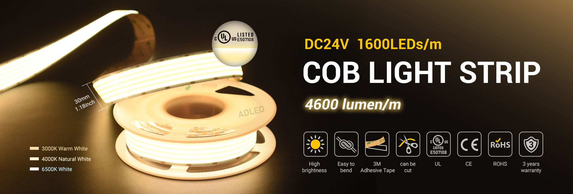
COB (Chip-on-Board) Architecture

Technical Comparison Matrix

Parameter SMD LED Strip COB LED Strip
Emitter Density
60–360 LEDs/m
Equivalent to 400–800+ micro-emitters/m
Visible Dotting
Noticeable at <1m viewing distance
Near-zero dotting; seamless diffusion
Optical Control
Requires external diffusers/channels for uniformity
Inherent diffusion; minimal secondary optics needed
Thermal Path
Chip → solder pad → copper trace → PCB → aluminum channel
Chip → die attach → substrate → aluminum channel
Cut Intervals
Every 25mm–100mm (voltage dependent)
Factory-segmented; limited field cutting
Failure Isolation
Single LED failure rarely affects adjacent emitters
Localized thermal runaway can propagate if undersized
Binning Requirement
High; SDCM control across batches essential
Moderate; phosphor matrix averages minor chip variance

Architectural Specification Takeaway

  • Specify SMD when routing complexity, field modifications, or accessory compatibility dictate flexibility.
  • Specify COB when visual seamlessness, low mounting height, or premium aesthetic integration are non-negotiable.
  • Verify substrate material (FR4 vs. aluminum vs. copper) and phosphor coating thickness in technical datasheets. Do not rely on marketing density claims.

Photometric Performance & Visual Quality

Architectural spaces demand controlled luminance, accurate color rendering, and minimal visual fatigue. Photometric metrics determine whether an LED strip meets professional standards or falls short in critical viewing zones.

Uniformity & Dotting Control

  • SMD LED strips exhibit periodic luminance peaks. At mounting distances <500mm, discrete emitters create visible hotspots without proper diffusion.
  • COB LED strips distribute photons across a continuous phosphor matrix. Luminance variance typically <5% across 1-meter spans when properly driven.
  • UGR (Unified Glare Rating) considerations: COB inherently reduces direct glare. SMD requires louvered channels, frosted diffusers, or indirect mounting to achieve UGR <19 in task-adjacent zones.

Color Rendering & Consistency

  • CRI Ra alone is insufficient. Require TM-30-15 data: Rf (fidelity) >90, Rg (gamut) 100–110 for architectural accuracy.
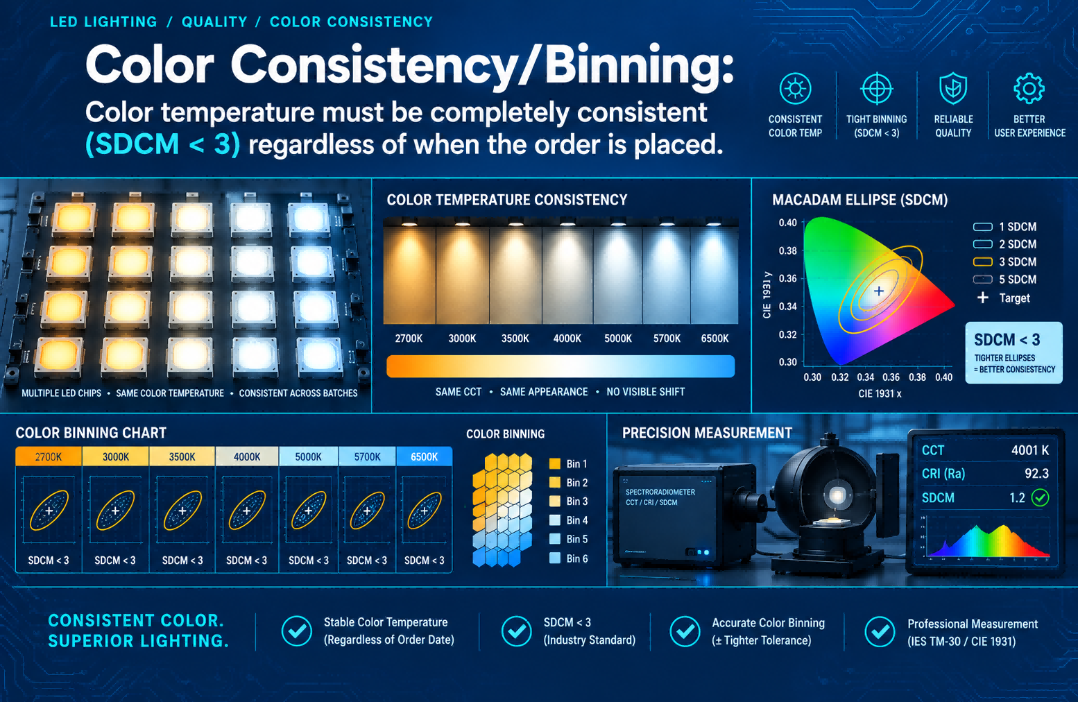
  • SDCM (Standard Deviation of Color Matching): Architectural grade requires ≤3 SDCM across entire production batch and over lifecycle.
  • COB phosphor blending naturally tightens SDCM. SMD requires strict binning and batch-matching during procurement.
  • CCT stability: COB exhibits slower CCT shift under thermal load due to uniform phosphor distribution. SMD shows localized shift if thermal management is inadequate.

Beam Distribution & Optical Efficiency

  • SMD: Typical 120°–140° lambertian emission. Secondary optics required for narrow beam control.
  • COB: 110°–130° natural spread. Higher optical efficiency in direct-view applications due to reduced reflection losses in diffuser layers.
  • Luminous efficacy comparison: Modern COB achieves 130–150 lm/W at rated current. High-density SMD reaches 140–160 lm/W but loses 15–25% efficacy when paired with architectural diffusers.

Field Validation Checklist

  • Request LM-79 photometric reports, not just catalog values
  • Verify integrating sphere testing at 25°C and 45°C ambient
  • Demand SDCM certification per IEC 60081 or ANSI C78.377
  • Cross-reference TM-30 Rf/Rg for material-critical spaces (retail, galleries, healthcare)
  • Test diffuser compatibility with actual LED strip samples before full procurement

Architectural Specification Takeaway

  • Use COB for close-proximity viewing, high-end interiors, glare-sensitive environments, and seamless linear accents.
  • Use SMD for long linear runs where external channels/diffusers are already specified, or where optical tuning is required per zone.
  • Never specify based on lm/W alone. Efficacy without uniformity or color stability fails architectural intent.

Thermal Management & Longevity

Heat is the primary degradation vector for LED performance. Junction temperature (Tj) directly dictates lumen maintenance, color shift, and driver lifespan. Thermal design separates commercial-grade products from architectural-grade systems.

Thermal Pathway Analysis

  • SMD: Heat transfers through solder joints → copper traces → PCB dielectric → adhesive → aluminum channel. Each interface adds thermal resistance (Rth). Typical Rth junction-to-ambient: 15–25°C/W.
  • COB: Direct die attachment to substrate eliminates solder and trace resistance. Rth junction-to-ambient: 8–14°C/W when mounted to thermally conductive profiles.
  • Thermal concentration: COB packs higher power density per linear meter. Requires precise channel cross-section and thermal interface material (TIM) application.

Lumen Maintenance & Degradation Curves

  • L70/L80 thresholds define architectural lifespan. Verify LM-80 data from chip manufacturer, not LED strip assembler.
  • SMD at 35°C ambient, 700mA/m: L70 typically reached at 50,000–60,000 hours with proper heat sinking.
  • COB at 35°C ambient, 800mA/m: L70 typically reached at 60,000–80,000 hours due to lower Tj and uniform phosphor aging.
  • Derating rule: Every 10°C above rated Tj reduces lifespan by ~50%. Architectural installations often exceed 40°C ambient in enclosed coves.

Thermal Interface Requirements

  • Aluminum channel thickness: Minimum 1.0mm for SMD, 1.2mm for COB at >14W/m
  • TIM specification: Silicone thermal pad (1.5–2.0 W/m·K) or phase-change material. Never use adhesive-only mounting.
  • Ventilation: Enclosed channels require passive vents or forced airflow if power density >18W/m.
  • IP rating impact: Silicone overmolding improves moisture resistance but traps heat. IP65+ COB requires derated current in confined spaces.

Field Installation Thermal Guidelines

  • Mount LED strips on continuous aluminum profiles, not drywall or wood substrates
  • Maintain 10–15mm clearance from insulation or vapor barriers
  • Use thermally conductive mounting tape rated for 100°C continuous operation
  • In high-ambient environments (>40°C), reduce drive current by 15–20% to preserve L80
  • Verify channel cross-section matches strip width; overhanging edges create thermal bottlenecks

Architectural Specification Takeaway

  • COB delivers superior thermal efficiency but demands precise channel integration and current control.
  • SMD tolerates looser mounting tolerances but loses longevity if installed without thermal management.
  • Always request thermal simulation files or channel compatibility matrices from manufacturers.
  • Specify L80@50,000h minimum for commercial architecture. L70 is unacceptable for high-spec projects.

Electrical & Installation Considerations

Architectural installations fail at the electrical interface, not the LED package. Voltage drop, dimming compatibility, circuit protection, and field splicing dictate long-term reliability.

Voltage Drop & Power Injection

  • SMD: Lower current density per segment. Voltage drop manageable with 50mm cut intervals. Power injection required every 5–8m for 24V systems.
  • COB: Higher continuous current draw. Voltage drop accelerates rapidly beyond 3m. Power injection required every 2.5–4m for stable luminance.
  • Calculation baseline: V_drop = (I × R × L) / 1000. Verify copper trace thickness (1oz vs 2oz) and operating current.
  • Architectural rule: Never exceed 5% voltage drop at end of run. Use 24V for runs >10m, 48V for >20m.

Cut Points & Field Modification

  • SMD: Clearly marked cut zones every 25–100mm. Solderless connectors available but increase failure points.
  • COB: Factory-segmented. Field cutting requires specialized tools and resealing. Improper cutting voids warranty and compromises IP rating.
  • Specify factory-precut lengths matching design drawings. Minimize field modifications for COB systems.

Dimming & Control Compatibility

  • SMD: Compatible with 0–10V, DALI, TRIAC, PWM, and wireless protocols. Wide driver ecosystem.
  • COB: Sensitive to low-frequency PWM. Requires constant-current drivers with smooth dimming curves (0.1–100%).
  • Flicker threshold: IEEE 1789 recommends Pst LM <1, SVM <0.4 for architectural spaces. Verify driver compatibility before procurement.
  • DALI-2 certification mandatory for commercial projects. Avoid generic PWM dimmers with COB.

Circuit Protection & Compliance

  • Overcurrent protection: Inline fuses or driver-level current limiting required for COB due to higher power density.
  • Surge protection: 1kV line-to-line minimum for indoor, 2kV for outdoor or exposed coves.
  • Compliance: UL 2108 (low voltage), IEC 60598-2-23, EN 61347-2-13. Verify certification marks, not just CE/RoHS.
  • Wiring: 18AWG minimum for <20W/m, 16AWG for >20W/m. Stranded copper required for vibration-prone zones.

Field Installation Protocol

  • Verify driver output matches strip current rating exactly
  • Measure voltage at start, midpoint, and end before final mounting
  • Use crimped or soldered connections; avoid push-in terminals for permanent installs
  • Seal all cut points with IP-rated silicone if environmental exposure exists
  • Document circuit layout, injection points, and driver specifications for maintenance teams

Architectural Specification Takeaway

  • COB requires precise electrical planning, factory-cut lengths, and high-quality constant-current drivers.
  • SMD offers greater field flexibility but increases splice points and potential failure nodes.
  • Always specify DALI-2 or certified 0–10V drivers for commercial architecture.
  • Voltage drop is the #1 cause of luminance inconsistency. Design circuits with injection points from day one.

Application-Specific Selection Guide

Architectural intent dictates technology selection. Matching LED architecture to spatial requirements prevents over-engineering, budget waste, and visual compromise.

Cove & Indirect Lighting

  • Requirement: Seamless luminance, low glare, hidden mounting
  • Recommendation: COB for <300mm mounting depth. SMD acceptable with frosted channels if depth >500mm.
  • Technical note: COB eliminates visible emitter shadows on adjacent surfaces.
Cove & Indirect Lighting

Linear Facade & Exterior Accent

  • Requirement: Weather resistance, long runs, maintenance access
  • Recommendation: SMD IP65/IP67 with aluminum channels. COB requires specialized sealing and thermal derating.
  • Technical note: SMD modular replacement reduces facade maintenance downtime.
Linear Facade & Exterior Accent

Retail & Display Lighting

  • Requirement: High CRI, accurate color, focused illumination
  • Recommendation: COB for close-range product viewing. SMD with optical lenses for directional highlighting.
  • Technical note: TM-30 Rg >100 enhances material saturation without distorting brand colors.

Hospitality & Ambient Zones

  • Requirement: Visual comfort, tunable white, low maintenance
  • Recommendation: COB for lobby, corridor, and guestroom ambient. SMD for bathroom vanity and task zones.
  • Technical note: COB phosphor uniformity supports consistent CCT mixing in tunable systems.
Hospitality & Ambient Zones

Museum & Gallery Lighting

  • Requirement: Zero UV/IR, precise SDCM, flicker-free operation
  • Recommendation: COB with museum-grade phosphor and IEEE 1789-compliant drivers. SMD only with secondary filtration and diffusers.
  • Technical note: Verify spectral power distribution (SPD) for UV/IR content <0.5%.

Decision Matrix for Specifiers

Application
Priority Metric
Recommended Technology
Installation Note
Low ceiling cove
Uniformity, UGR
COB
Mount to continuous aluminum profile
Long corridor run
Voltage stability, cost
SMD
Power inject every 5m, 24V system
Retail display
TM-30, close viewing
COB
Use anti-glare diffuser, <200mm distance
Outdoor facade
IP rating, serviceability
SMD
Sealed channels, modular replacement
Tunable ambient
CCT consistency, dimming
COB
DALI-2 driver, matched phosphor batches
Task lighting
Beam control, efficacy
SMD
Narrow channel, optical lens integration

Architectural Specification Takeaway

  • Never default to a single technology across an entire project. Match LED strip type to spatial function.
  • COB excels in visual quality and premium integration. SMD excels in flexibility and serviceability.
  • Document technology selection per zone in lighting control schedules and maintenance manuals.

Cost, ROI & Procurement Strategy

Upfront price rarely reflects total cost of ownership. Architectural procurement requires lifecycle analysis, warranty validation, and supply chain transparency.

Initial Cost Breakdown

  • SMD: Lower per-meter cost. Higher accessory dependency (channels, diffusers, connectors).
  • COB: Higher per-meter cost. Lower accessory dependency. Premium packaging and testing add value.
  • Accessory multiplier: SMD systems often cost 1.3–1.6× more when channels, diffusers, and installation labor are included.

Lifecycle Cost Analysis

  • Replacement labor dominates long-term cost. COB L80@60,000h reduces maintenance cycles by 30–40% vs SMD L70@50,000h.
  • Driver compatibility: High-quality COB-compatible drivers cost 15–20% more but reduce flicker complaints and warranty claims.
  • Energy savings: 5–10% lower lumen depreciation in COB offsets higher initial cost within 3–5 years in commercial operations.

Warranty & Verification Protocol

  • Standard warranty: 3–5 years commercial, 5–7 years architectural grade.
  • Void conditions: Improper thermal mounting, voltage drop >5%, non-certified drivers, field cutting COB.
  • Verification steps:
    1. Request LM-80 reports from chip supplier (not assembler)
    2. Cross-reference LM-79 photometric data with claimed values
    3. Verify thermal interface compatibility documentation
    4. Request batch SDCM certification for entire project quantity
    5. Confirm driver compatibility list matches control system spec

Procurement Risk Mitigation

  • Avoid single-source dependency for critical projects. Qualify 2–3 manufacturers with identical thermal/optical specs.
  • Require pre-production samples for photometric and thermal testing before bulk order.
  • Specify tolerance bands: ±3% lumen, ±2 SDCM, ±5% voltage drop at rated length.
  • Include lifecycle replacement clause in contract: manufacturer supplies matching batch for warranty claims.

Architectural Specification Takeaway

  • COB delivers lower total cost of ownership in high-spec, long-lifecycle projects.
  • SMD suits budget-constrained or highly modular installations where accessories are already specified.
  • Always procure based on verified test data, not catalog claims. Include LM-80, LM-79, and SDCM documentation in tender packages.
  • Warranty value is meaningless without thermal and electrical compliance documentation.

Future Trends & Industry Standards

Architectural lighting is shifting toward human-centric design, smart integration, and sustainability compliance. Technology selection must anticipate regulatory changes and performance expectations.

Human-Centric & Tunable Systems

  • COB phosphor matrices enable smoother CCT transitions and reduced color banding in tunable white systems.
  • SMD requires careful bin matching across CCT ranges. Mixed batches cause visible transition lines in architectural spaces.
  • Standard emerging: IEC 62717 for tunable LED modules. Specify compliance for dynamic lighting zones.

Smart Integration & Protocol Compatibility

  • DALI-2, Zigbee 3.0, and Thread/Matter adoption rising in commercial architecture.
  • COB LED strips require drivers with advanced dimming resolution (12-bit minimum) to prevent stepping in low-light scenes.
  • SMD integrates more easily with legacy TRIAC and 0–10V systems. Bridge protocols often required for COB retrofits.

Sustainability & Compliance

  • RoHS 3.0, REACH SVHC, and WEEE directives tightening. Verify mercury-free phosphor and halogen-free PCB substrates.
  • Recyclability: Aluminum channel integration simplifies end-of-life separation. Silicone overmolding complicates recycling.
  • EPD (Environmental Product Declaration) becoming mandatory in EU and North American green building certifications.

Standardization Gaps & Industry Direction

  • Lack of unified COB density classification creates specification confusion. Industry moving toward lm/m per linear meter standardization.
  • Thermal simulation files (STEP/IGES) increasingly requested by BIM workflows. Manufacturers must provide channel compatibility libraries.
  • 2025–2026 trend: High-density COB replacing SMD in premium architectural applications due to visual seamlessness and lower maintenance burden.

Architectural Specification Takeaway

  • Future-proof projects by specifying DALI-2 compatibility, LM-80 verification, and EPD documentation.
  • Require BIM-ready channel models and thermal simulation data from manufacturers.
  • Monitor IEC and ANSI updates for tunable white and human-centric lighting standards.
  • COB will dominate high-spec architectural zones. SMD will remain viable for modular, outdoor, and retrofit applications.

Summary

COB and SMD LED strips serve distinct architectural functions. COB delivers seamless luminance, superior thermal efficiency, and lower long-term maintenance, making it ideal for premium interiors, close-range viewing, and glare-sensitive environments. SMD offers routing flexibility, easier field modification, and broader driver compatibility, suiting long linear runs, outdoor applications, and budget-conscious projects. Selection must be driven by photometric requirements, thermal management capabilities, electrical planning, and lifecycle cost analysis. Verify all claims with LM-79, LM-80, SDCM, and TM-30 data. Specify appropriate channels, drivers, and installation protocols from project inception. COB reduces visual compromise but demands precise engineering. SMD increases adaptability but requires rigorous accessory integration. Architectural lighting success depends on matching technology to spatial intent, not catalog convenience.

FAQ

Can COB LED strips be cut on-site like SMD LED strips?

No. COB LED strips have factory-defined segments. Field cutting damages the phosphor matrix and voids warranty. Specify exact lengths during procurement.

Does COB really eliminate dotting, or is it just marketing?

Verified COB LED strips with uniform phosphor coating show <5% luminance variance across 1m. Dotting is effectively eliminated at mounting distances >200mm.

Which technology is better for outdoor architectural lighting?

SMD IP65/IP67 with sealed aluminum channels. COB requires specialized sealing and thermal derating, making SMD more reliable for exterior exposure.

How do I verify true CRI and color consistency?

Request LM-79 reports, TM-30 Rf/Rg data, and SDCM ≤3 certification. Catalog Ra values alone are insufficient for architectural specification.

Can I use standard TRIAC dimmers with COB LED strips?

No. COB requires constant-current drivers with smooth dimming curves. TRIAC causes flicker, color shift, and premature failure. Use DALI-2 or certified 0–10V.

What is the minimum aluminum channel thickness for COB?

1.2mm for <14W/m, 1.5mm for >14W/m. Include thermal interface material. Undersized channels cause thermal runaway and lumen depreciation.

Is COB more expensive long-term than SMD?

No. Higher initial cost is offset by 30–40% lower maintenance cycles, reduced accessory dependency, and longer L80 lifespan in commercial environments.

How do I prevent voltage drop in long COB runs?

Use 24V or 48V systems, inject power every 2.5–4m, verify 2oz copper traces, and measure voltage at multiple points before final installation.

Can COB and SMD be mixed in the same project?

Yes, but not in the same visual zone. Match technology to spatial function. Document differences in lighting schedules to avoid maintenance confusion.

What documentation should I require from manufacturers?

LM-80 chip reports, LM-79 photometric data, SDCM certification, TM-30 metrics, thermal compatibility matrices, driver compatibility lists, and IP rating test reports.
Contact ADLED for LED Strip Light